With OpenGL 4.3, we finally have access to compute shaders and all of the glorious GPGPU functionality that modern hardware allows. Now, I have done some work with OpenCL before but having compute functionality that is properly integrated into the OpenGL pipeline was what finally convinced me that I should take a stab at writing a real time ray tracer that runs on the GPU.
Let's get started!
What I'm going to show you here is an introduction to the general idea of the technique, the code framework and some fundamental math required in order for us to get a basic ray tracer up and running with compute shaders. As the series progresses we'll cover more advanced topics.
What Do You Need To Know?
I am assuming that the reader is familiar with intermediate linear algebra, OpenGL
and its associated shading language GLSL, some 3D mathematics (camera transforms, coordinate spaces, projection transforms etc), and basic lighting calculations. I'd love to make posts that cover all of these required topics, but I'm afraid that approaches writing a book in scope, which would require me to quit my day job and charge everyone for this! If you're not yet comfortable with those topics, go run through some of those tutorials first, perhaps get a good book or two (some are listed in my previous posts if I remember correctly), and then come on back :)
What Is Ray Tracing?
In order to properly explain what ray tracing is, we need to do a quick summary of the relevant aspects of computer graphics.
Our modern computer imagery is what you would call
raster based. This means that our images consist of a generally rectangular arrangement of discrete picture elements. So all image generation algorithms we care about create images by populating each of these raster elements with a certain color.
Up until recently, rendering raster computer graphics in real time has been done mostly (pretty much exclusively) by a technique called rasterization. Rasterization is an example of an object order algorithm, whereby to draw a scene, you iterate over all of the objects in the scene and render them accordingly. The "objects" we are referring to are geometric primitives (usually triangles) which are projected onto the image plane, after which the spans of pixels that those objects cover are filled in. GPUs were initially created to perform this rasterization, and its associated operations, in hardware.
The reason why rasterization has been the preferred approach to real time rendering thus far is because the algorithm simplifies rendering in several ways, and exploits the principle of coherence to increase efficiency beyond any other approach. An explanation is beyond the scope of this post, but please check the further reading section. Primitives and their associated spans of fragments (potential pixels) are rendered in isolation, without needing to be aware of other scene elements. The results are then converged at appropriate places in the pipeline to ensure that the final image is correct.
 |
Example of a modern rasterization pattern.
This pattern is to maximize memory coherency, which helps the algorithm's
efficiency on modern GPU memory architectures.
Image: IEEE Xplore |
However, because rasterization relies on several simplifying assumptions, it gets far more complicated to do complex effects. For instance, implementing correct transparency and reflections are hard to do with the traditional rasterization approaches. Phenomena like shadows, are done using various techniques that can be quite fragile and require a good deal of tweaking to look acceptable. Other phenomena like ambient occlusion are sometimes done using screen space information only. Furthermore, as geometry density increases and triangles become less than a pixel in size, modern rasterization hardware efficiency decreases.
Ray tracing takes a fundamentally different approach to generating images. Ray tracing is an image order algorithm, which means that instead of iterating over objects in the scene, you iterate over the image elements (pixels) themselves. The way ray tracing works is that for every pixel in the scene, you shoot a ray from the camera point through its position on the projection plane and into the scene. There the ray can intersect with scene geometry. From the intersection point on the geometry you are then free to perform shading calculations and/or reflect the ray off into the scene further. Ray tracing is a more physically accurate method of generating images as the rays themselves are aware of all of the elements of the scene and the algorithm can take this into account when performing its calculations. For instance, when a ray intersects a curved transparent object, the ray itself can refract through the object and into the scene again, resulting in properly simulated light refraction. Another example would be how shadows are calculated, instead of using volume or raster based approaches, you simply cast a ray from the point on the object towards a prospective light source, and if the ray intersects some geometry, that point is in shadow.
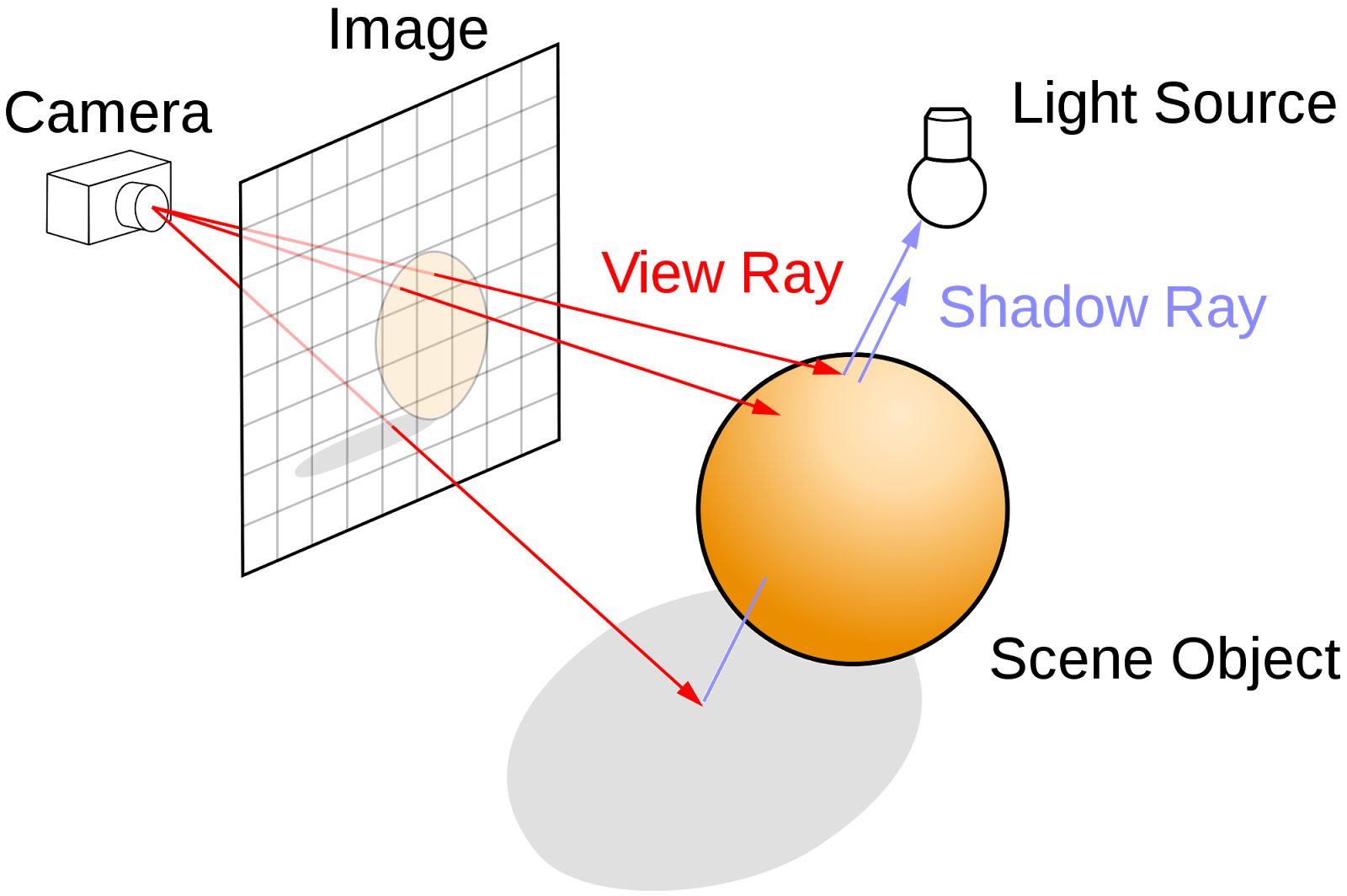 |
Ray tracing algorithm illustrated.
Image: Wikipedia |
Ray tracing is less efficient than rasterization for generating images, especially as more complicated effects require that several rays being cast per pixel. It can require many more calculations per pixel, and because rays can be wildly divergent in terms of what they hit, it doesn't exploit coherence well. However, it is far simpler to model complex phenomena, and the algorithm scales well to parallel hardware architectures. In fact, ray tracing belongs to that rare breed of algorithm that scales almost perfectly linearly with the amount of processing elements that it is given. It is partially because of these reasons that ray tracing (or related techniques) is preferred over rasterization for offline, photo-realistic rendering.
Of course, no technique exists alone in a vacuum, and there have been several hybrid approaches that try to combine the best of both rasterization and ray tracing. Newer PowerVR demos are utilizing what appears to be hardware accelerated ray tracing for transparencies, reflections and shadow calculations. A few other approaches worth mentioning, as dangling threads to follow up for the interested, are
Voxel Cone Tracing for global illumination and
Sparse Voxel Octrees for infinite geometric detail.
I should add here that another advantage that ray tracing could be said to have is that it is not restricted to rasterizable geometry (pretty much only triangles). However, for much of my purposes this is mostly useless. Most realistic scenes don't consist solely of "pure math objects" like spheres and tori!
Further Reading
http://ocw.mit.edu/courses/electrical-engineering-and-computer-science/6-837-computer-graphics-fall-2012/lecture-notes/MIT6_837F12_Lec21.pdf
http://ieeexplore.ieee.org/ieee_pilot/articles/96jproc05/96jproc05-blythe/article.html#fig_6
http://en.wikipedia.org/wiki/Cone_tracing
http://blog.imgtec.com/powervr/understanding-powervr-series5xt-powervr-tbdr-and-architecture-efficiency-part-4
https://www.youtube.com/watch?v=LyH4yBm6Z9g
http://www.eetindia.co.in/ART_8800696309_1800012_NT_e092890c.HTM
GPU Hardware Evolution and the Emergence of Compute
We now have an idea of what ray tracing is and how it differs from rasterization. But how will it be possible to accelerate this algorithm on hardware that was architected to accelerate the rasterization
algorithm? Let's cover some history quickly.
The first truly integrated GPU that contained all components of the graphics pipeline in hardware can be traced back to as recently as late 1999 with the release of the GeForce 256. Previous video cards lacked hardware acceleration of some stages like Transform and Lighting (T&L) and therefore could not be considered true GPUs. Further development of the GPU would see the addition of multiple parallel processing units that exploited the parallelism of computer graphics operations. For example, having more than one T&L engine that could process several vertices at once. Or more than one pixel engine that could process several fragments at once. These early GPUs were fixed function as the operations that they performed on data were predetermined in hardware with very limited customizability.
The next evolution for GPUs was the addition of programmable stages in the graphics pipeline. Hardware T&L was replaced with vertex shaders, and pixel engines were replaced with fragment shaders. These vertex and fragment shaders were programs, written in a shading language that would execute on the data being fed to the graphics pipeline, allowing for custom operations to be performed.
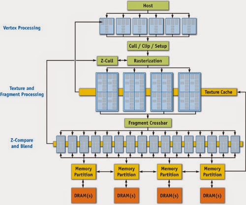 |
GeForce 6 Series Architecture
Here you can see the parallel and programmable processing units used for vertex and fragment processing.
Image: Nvidia |
In addition to this programmability, hardware vendors soon realized that they could cater to the needs of both vertex shading and fragment shading with one hardware core, and unified shaders were born. This trend towards increasingly general computation and unified hardware compute units has led to the modern style of graphics processor, which can be considered a massive array of general compute resources (a sea of processors) that have specific graphics related hardware attached (texture sampling units etc). Because of all this general purpose compute power available, APIs like OpenCL have been created that can take advantage of the GPU not for graphics but for general compute tasks. Although it's important to note that OpenCL isn't built for GPUs specifically. It's built to enable parallel heterogeneous computing on a wide variety of different hardware, including CPUs and DSPs.
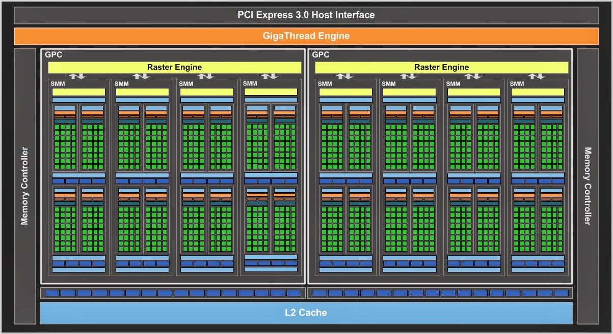 |
Nvidia Maxwell Architecture Diagram
Note the shift away from specialized processing units to more general units.
Image: Nvidia |
The latest OpenGL version (4.3 at the time of writing) provides a feature called Compute Shaders, which are written in the OpenGL shading language but are capable of performing general computations that need not be related to rendering at all, and are not bound to a particular stage of the graphics pipeline. The big positive is how tightly integrated this functionality is with traditional OpenGL functionality. There is no need to mess around with OpenCL-OpenGL interop and contexts etc. We can use this compute functionality to do pretty much anything so long as we can express the problem in the right way. Fortunately a ray tracer is easy to express with compute shaders. We'll cover how to accomplish this in code later.
Further Reading
http://www.nvidia.com/content/GTC-2010/pdfs/2275_GTC2010.pdf
http://www.techspot.com/article/650-history-of-the-gpu/
Code Architecture Quick Description
Firstly, you should download the code and assets
here
I won't cover all of the code (you can just download it and see it for yourself) but I will go through some of the various pieces to help you understand everything. The usual disclaimer about "use the code for whatever you want but don't blame me if something goes wrong" applies. The code was written with Visual Studio 2013 so you'll need that version or newer to open up the solution file.
Let's cover main.cpp first:
This is obviously the entry point for the application. I used SDL 2 and glew to handle all of the OpenGL and window related set up that we need.
Let's cover the interesting code:
    CameraLib::Camera camera;
    camera.ResetCameraOrientation();
    camera.SetPosition(0.0f, 0.0f, 50.0f);
    camera.SetCameraYFov(60.0f);
This sets up the camera that we'll view the scene from. My camera system is based on the OpenGL camera system exactly, as in, it is righ
t handed and the negative z-axis in camera space contains the visible parts of the scene. The Camera class contains all of the math required to set up the camera in the virtual scene and provides convenience methods for transforming between camera and world space (as well as frustum generation methods for frustum culling etc, but that's not really useful to us for now).
Raytracer::CameraControl cameraControl(camera);
This is the simple update mechanism for the camera in the scene (the camera is used by the CameraControl object and also by the ray tracer itself). The main loop accepts SDL key commands and sets state on this object, which then updates the camera every frame. Simple simple!
    Raytracer::Raytracer raytracer;
    raytracer.ResizeViewport(1280, 720);
    raytracer.SetCamera(&camera);
This sets up the ray tracer itself, as you can see, I've hard coded the resolution to be 1280 by 720 for now. Also, we give the ray tracer a const pointer to the camera so that it can determine where the scene is being viewed from.
    MathLib::quaternion identityQuaternion;
    MathLib::quaternion_setToIdentity(identityQuaternion);

    Assets::MeshManager::GetInstance().SetMeshDatabase("test.mdb");

    // Prepare scene geometry.
    raytracer.ClearSceneData();
    Raytracer::StaticMeshInstance meshInstance("monkey",
                                               MathLib::vector4(0.0f, 0.0f, 0.0f, 1.0f),
                                               identityQuaternion,
                                               5.0f);
    raytracer.AppendStaticMeshInstanceToSceneData(meshInstance);
    raytracer.CreateNewSceneDataSSBO();
Ok now here is where things get tricky. I use my good old trusty math library (see my first two posts ever) pretty much in all of my 3D projects. Here you can see, I create an identity orientation quaternion.
Then afterwards you can see that I initialize something called a mesh database. What this is, is that ray tracing spheres is pretty damn boring, and it's also not very useful. Most of the cool geometry created by artists or modellers these days is mesh based. So I hijacked the asset code from my main project to load up some triangle meshes for me to use.
Then after that, you can see I clear any scene data the ray tracer might have, instantiate an instance of a mesh called "monkey" at a basic orientation and position in the world and load the ray tracer with it before rebuilding something called a "Scene Data SSBO". What's happening here?
Firstly, the way I architected the ray tracer for now (and bear in mind that this is NOT the right way to go about it, but is quick and easy for me and you first time around :) ) is that all the ray tracer sees is a giant list of triangles in world space that it then intersects its rays with. So what is happening is that the ray tracer is taking the mesh instance and transforming all of it's triangles into world space and storing them in a big list somewhere, before transferring them to this SSBO thing. What is that?
That's a Shader Storage Buffer Object, and it's a new feature in OpenGL 4.3 that lets you create arrays of data and, in a shader, read those arrays of data as C-struct like arrays. It's how we can give data to the ray tracer without it being a set of hard coded spheres like every first ray tracer demo...
After that's done the main loop begins and we are away.
Raytracer class:
The ray tracer itself is ridiculously simple at heart, let's look at the main loop for instance:
    void Raytracer::Render()
    {
        RaytraceScene();

        TransferSceneToFrameBuffer();
    }
That's all it does guys (aside from the mundane setting up operations etc).
But to be more specific, what is actually going on is RaytraceScene() executes a compute shader which has access to that flat list of world space triangles and some camera parameters (which I'll explain later). That compute shader writes to a texture object using some new GLSL image store operations. And after that's done, we simply draw that texture over the screen as a quad.
Couldn't be simpler.
Having said that there is some OpenGL 4.3 specific stuff happening and it's beyond the scope of this post to be an OpenGL tutorial as well... I will however link to some in the further reading section. Generally though, if there's something you don't understand, just Google the function call and investigate around, it's all straight forward.
Shaders:
In the code there's also ShaderManager/ShaderProgram/Shader classes. These are just typical convenience classes used to load up shader files, compile them, link them, and provide methods to set uniform variables of various data types. The code is fairly straight forward and is lifted from my other projects (albeit expanded to support compute shaders as well).
Further Reading
http://web.engr.oregonstate.edu/~mjb/cs475/Handouts/compute.shader.1pp.pdf
https://www.opengl.org/wiki/Compute_Shader
http://www.geeks3d.com/20140704/tutorial-introduction-to-opengl-4-3-shader-storage-buffers-objects-ssbo-demo/
Generating Rays
The first piece of magic that we're going to need here is the ability to generate for every pixel on the screen, an appropriate viewing ray in world space.
Specifically, we need a mechanism that:
Takes a window coordinate, in our case a value in the range [0, 1280) for the x-axis, and [0, 720) for the y-axis, and generates a ray world space for us. We are going to accomplish this with the use of two matrix transforms that can happen in the compute shader for every pixel.
The first transform that we're going to need is one that, given a 4D vector <xcoord, ycoord, 0, 1>, gives us the location in camera space of the associated point on the near projection plane.
This is better explained with the aid of a diagram, and in two dimensions.
Say we have the window coordinate < don't care, 0 > (which is any pixel on the top scan line of your display, remember pixels increase their position as they move to the bottom right of the screen). What we want for that y coordinate is to get the top value on our near clipping plane.
We're going to accomplish this in two steps.. firstly we're going to map the range in window coordinates from [0, width) and [0, height) to [-1, 1] each.
Following this with a scale to the top (and for the x-axis values, right) values (my camera system uses a symmetric frustum so the left most value is simply -right).
Firstly, we stick our window coordinate in a 4D vector <xcoord, ycood, 0, 1>.
Then we'll have the normalization matrix which get's us to the range [-1, 1]:
            MathLib::matrix4x4 screenCoordToNearPlaneNormalize
            (
                2.0f / (m_ViewportWidth - 1.0f), 0.0f, 0.0f, -1.0f,
                0.0f, -2.0f / (m_ViewportHeight - 1.0f), 0.0f, +1.0f,
                0.0f, 0.0f, 0.0f, -nearPlaneDistance,
                0.0f, 0.0f, 0.0f, 1.0f
            );
After that we need a transform to map that normalized set of values to the correct near plane dimensions:
            float aspectRatio = (float)m_ViewportWidth / (float)m_ViewportHeight;

            float halfYFov = m_Camera->GetYFov() * 0.5f;

            float nearPlaneDistance = m_Camera->GetNearClipPlaneDistance();
            float top = nearPlaneDistance * tan(MATHLIB_DEG_TO_RAD(halfYFov));
            float right = top * aspectRatio;

            MathLib::matrix4x4 screenCoordToNearPlaneScale
            (
                right, 0.0f, 0.0f, 0.0f,
                0.0f, top, 0.0f, 0.0f,
                0.0f, 0.0f, 1.0f, 0.0f,
                0.0f, 0.0f, 0.0f, 1.0f
            );
These two matrices combine to give us our first required matrix:
            MathLib::matrix4x4 screenCoordTransform;
            MathLib::matrix4x4_mul(screenCoordToNearPlaneScale, screenCoordToNearPlaneNormalize, screenCoordTransform);
Excellent, now that we can get the position on the near plane for every pixel on the screen, all that is required is to be able to transform this into world space. But remember, we need to build a ray here, so what we need is to consider the position on the near plane as a
direction. So we need to simply transform this by the camera's orientation matrix:
            // Now we need to transform the direction into world space.
            auto& cameraXAxis = m_Camera->GetXAxis();
            auto& cameraYAxis = m_Camera->GetYAxis();
            auto& cameraZAxis = m_Camera->GetZAxis();

            MathLib::matrix4x4 rotationTransform
            (
                cameraXAxis.extractX(), cameraYAxis.extractX(), cameraZAxis.extractX(), 0.0f,
                cameraXAxis.extractY(), cameraYAxis.extractY(), cameraZAxis.extractY(), 0.0f,
                cameraXAxis.extractZ(), cameraYAxis.extractZ(), cameraZAxis.extractZ(), 0.0f,
                0.0f, 0.0f, 0.0f, 1.0f
            );
Now that we have the two required transforms, all we do is send them to the compute shader as uniforms:
            GLfloat matrixArray[16];
            screenCoordTransform.setOpenGLMatrix(matrixArray);
            shader->SetUniformMatrix4fv("u_ScreenCoordTransform", matrixArray);

            rotationTransform.setOpenGLMatrix(matrixArray);
            shader->SetUniformMatrix4fv("u_RotationTransform", matrixArray);
Inside the shader itself we can do the following to get our screen ray:
    // Acquire the coordinates of the pixel to process.
    ivec2 texelCoordinate = ivec2(gl_GlobalInvocationID.xy);

    vec4 screenRay = vec4(texelCoordinate.x, 720 - texelCoordinate.y, 0.0, 1.0);        // Need to flip y here.
    screenRay = u_ScreenCoordTransform * screenRay;

    // Set to vector for the rotation transform.
    screenRay.w = 0.0f;
    screenRay = u_RotationTransform * screenRay;
    screenRay.xyz = normalize(screenRay).xyz;
Why do we need to flip the texelCoordinate.y value? Simply because in window coordinates when y is 0 that is the top of the screen, but in my texture space the top row of texels is marked with the v coordinate at 1.0.
Ray-Triangle Intersection
The next and final piece of the ray tracer that we're going to need is the ability to intersect rays with triangles. In addition to that we need to be able to compute the barycentric coordinates to calculate interpolated values for texture coordinates and surface normals. A popular algorithm for this is the Möller–Trumbore intersection algorithm found
here.
The only change you need to be aware of in my code is that because I use clockwise vertex winding for my triangles a couple of things are swapped around.
The Core Loop of the Ray Tracer
Now that we have the ability to fire a ray off into the scene and hit something and get the interpolated result, we need to assemble all of
that logic to produce a coherent picture.
I'm going to cover the actual different algorithm types in future posts, but for now all our ray tracer is going to do is find the
closest triangle to a pixel, get it's
interpolated normal value and
shade that based on some light. To get the closest triangle to a pixel a simple naive loop like this will suffice.
given a ray in the scene
given a set of triangles
initialize some value t to be very large
initialize some index value to be -1
for each triangle in the scene
intersect ray with the triangle, determine the t_intersect value for that triangle if there is one
if there is an intersection
if the t_intersect triangle value is less than t
then set the old t to the t_intersect value and set the index to the currently intersected triangle
if index > -1
shade the triangle at the given index
Note:
In order for us to properly shade the triangle at the given point we're going to need to keep track of the barycentric coordinates returned from the ray-triangle intersection function as well. Then we can calculate the correct interpolated normal and, if we so choose, extra things like texture coordinates.
Trace That Monkey!
That's essentially all of the core features you need to get a basic ray tracer up and running. The only time-consuming part is the code implementation. Here's a screenshot of the final application running with the Suzanne or "Blender Monkey" mesh.
Performance and Quality
I need to add an entirely separate paragraph here to highlight the performance of our first implementation. On a GTX 760, which is no push-over card, to ray trace a simple, one-mesh scene like this consumes around 50ms. That is around 20 hertz. This falls into the "barely real-time" range of performance. Considering that a mesh with this complexity and simple shading would take an almost infinitesimal amount of time if we were to simply rasterize it this is rather disheartening isn't it?
Well, let us look at it this way:
The triangle count for the scene is just under 1000 triangles, and for every pixel on the screen we run through the entire list of triangles and attempt to intersect with them. This is as naive as a triangle ray tracer is going to get so it's no great wonder that it is so slow. The performance, however, is not a concern for this first post because as the series progresses, we shall be evaluating various methods to speed up our basic ray tracer, as well as add more features to it as we go along.
Also worth mentioning here, and you may see this when you move around in the demo, is that
sometimes there will be a missed pixel i.e. a pixel that should be shaded but the ray didn't hit any geometry. This is probably due to floating point inaccuracies in instancing every single triangle into world space. In future, rays will be transformed into model space, but that's for the next article!
Conclusion
In summary, we have covered what ray tracing is, and how it differs from rasterization. We have covered the hardware evolution and API features that allow us access to the required computing power and functionality to do it in real time. The fundamental simplicity of ray tracing means that we can cover the required mathematics for it fairly quickly. And we have established a first prototype that we can take forward and improve upon. We have opened the door into a huge body of work that we can look into and do some really interesting things with :)

